
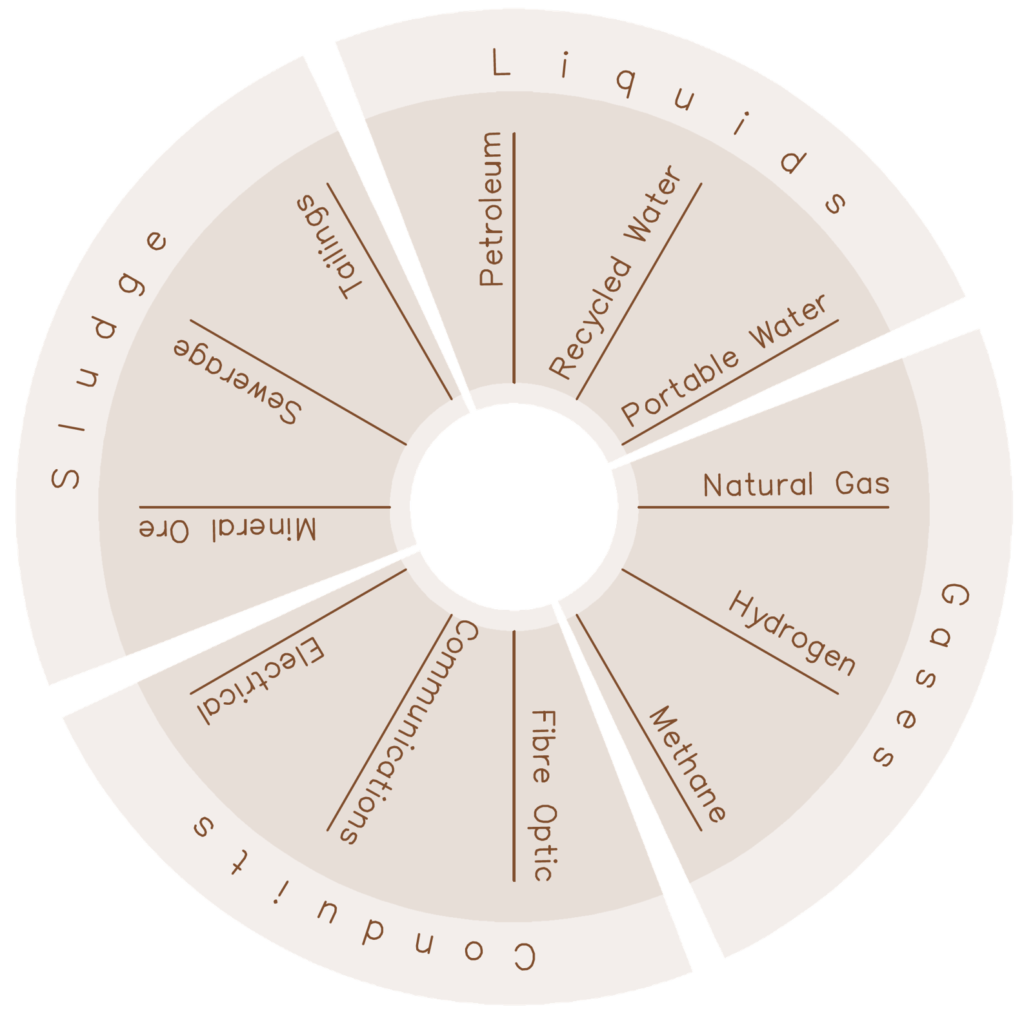
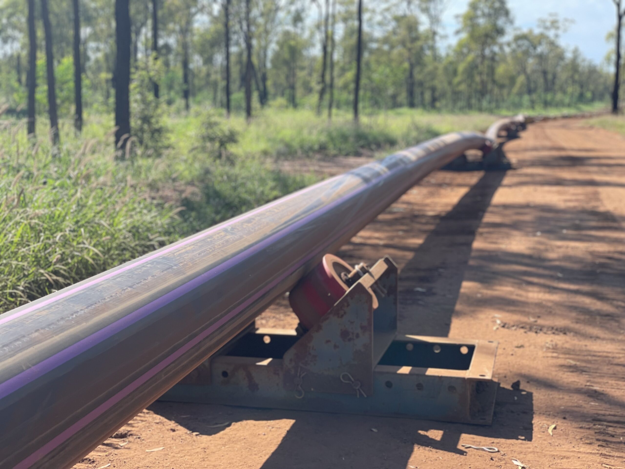
Pipelines are used to transport a variety of fluids such as gases and liquids over long distances and act as a protective conduit for sensitive cables.
They are predominately buried underground to protect the service from damage and enable surface use for other purposes.
Trenchless pipe installation methods are a rapidly growing sector of the civil construction industry. They can be used to install new pipelines or to replace and rehabilitate existing infrastructure.
The majority of pipelines are installed underground to provide protect the pipe and allow the surface to be utilised for other purposes. The traditional (trenched) way to install a pipe underground includes digging a trench, laying product pipe in the trench, and backfilling it. Pipeline routing has to account for land ownership, environmental obstacles, surface infrastructure, and subsurface infrastructure. This has led to the development of trenchless pipe installation methods.
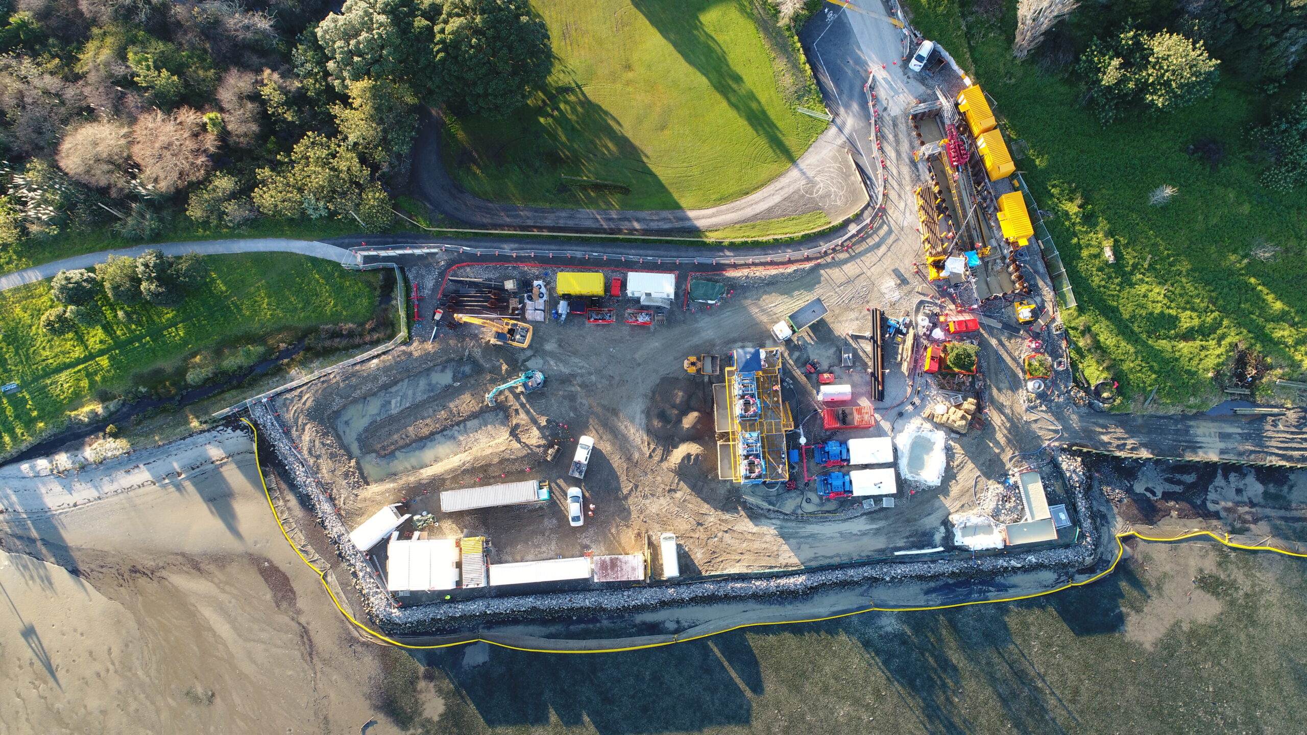
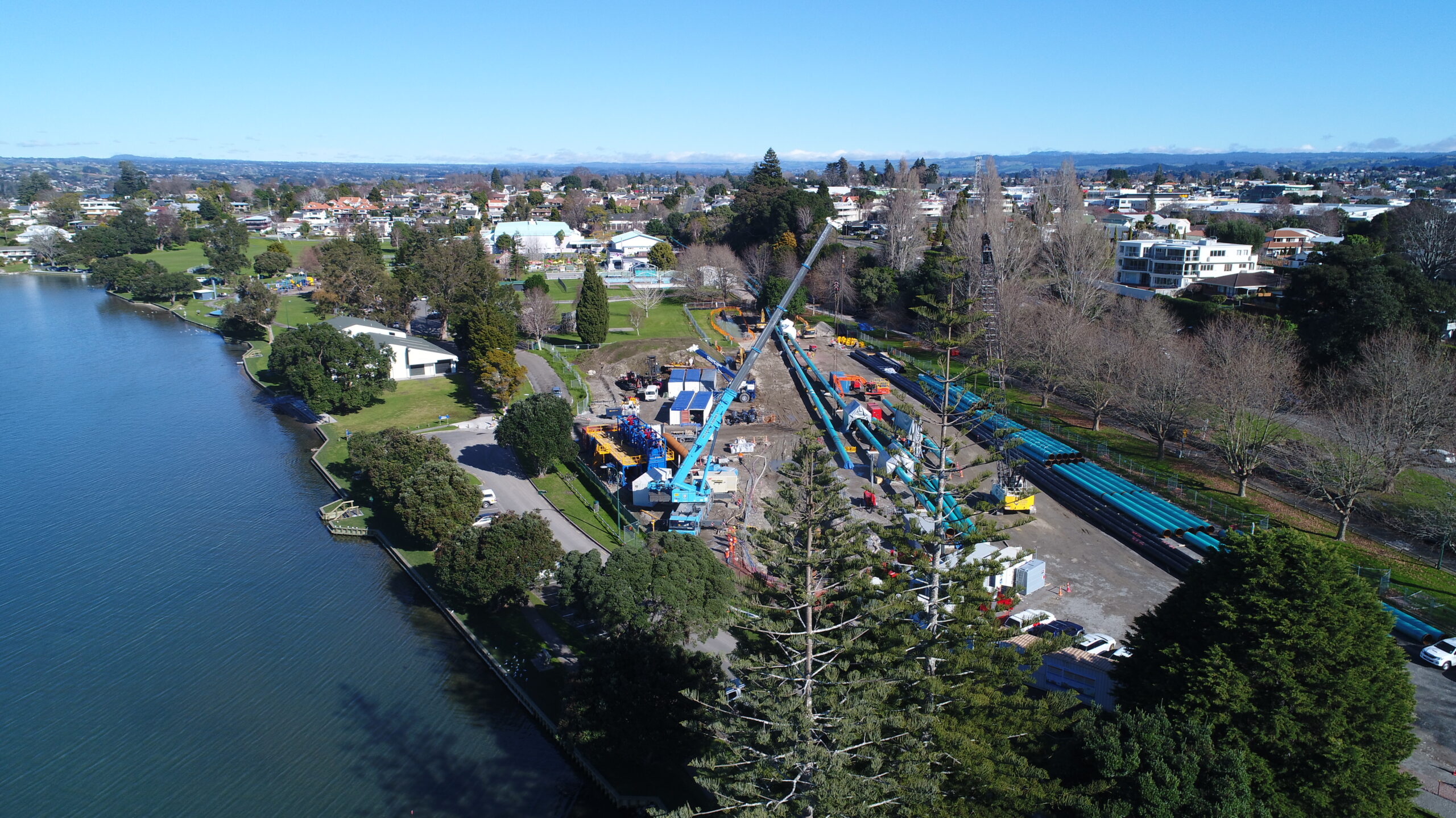
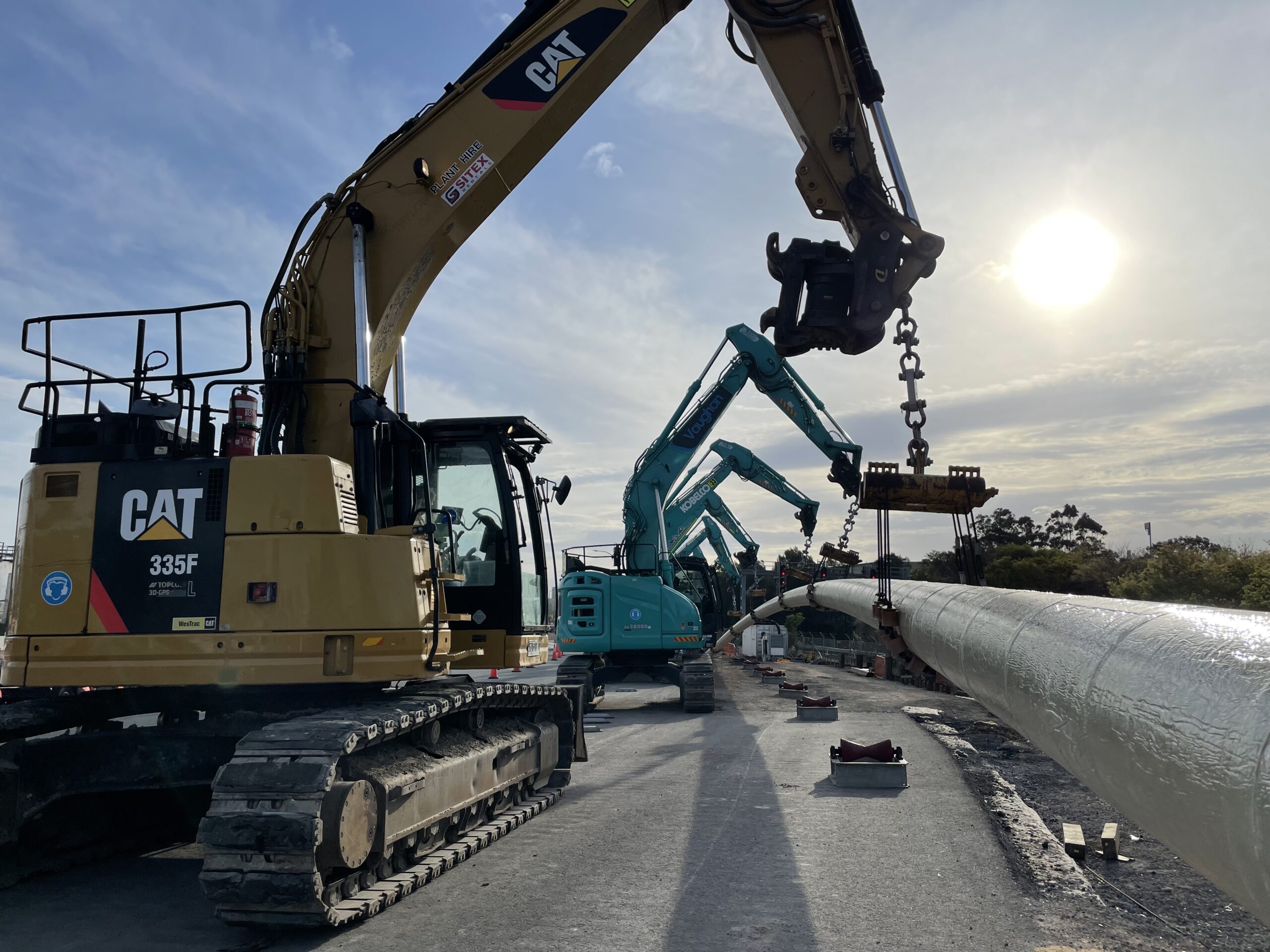
Trenchless pipe installation allows a pipe to be installed from point A to point B with minimal surface excavation impact along the route. Most of the construction works are undertaken at point A, the launch/ entry location, and point B the receival/ exit location, with remote installation occurring between these two points.
In summary, the benefits of trenchless installation methods include:
- Minimal excavation
- Natural obstacles such as rivers, or environmental protection zones are to remain undisturbed
- Impact to surface transport (road, rail, pedestrians) is limited
- Deeper crossings to design around existing structures and services
- Minimise impact to landowners
- Cost benefits where pipeline routes navigate difficult terrain, densely trafficked areas, high water tables, and unstable geotechnical conditions

Trenchless Methods
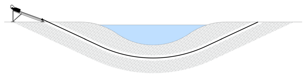
HDD – Horizontal Directional Drilling
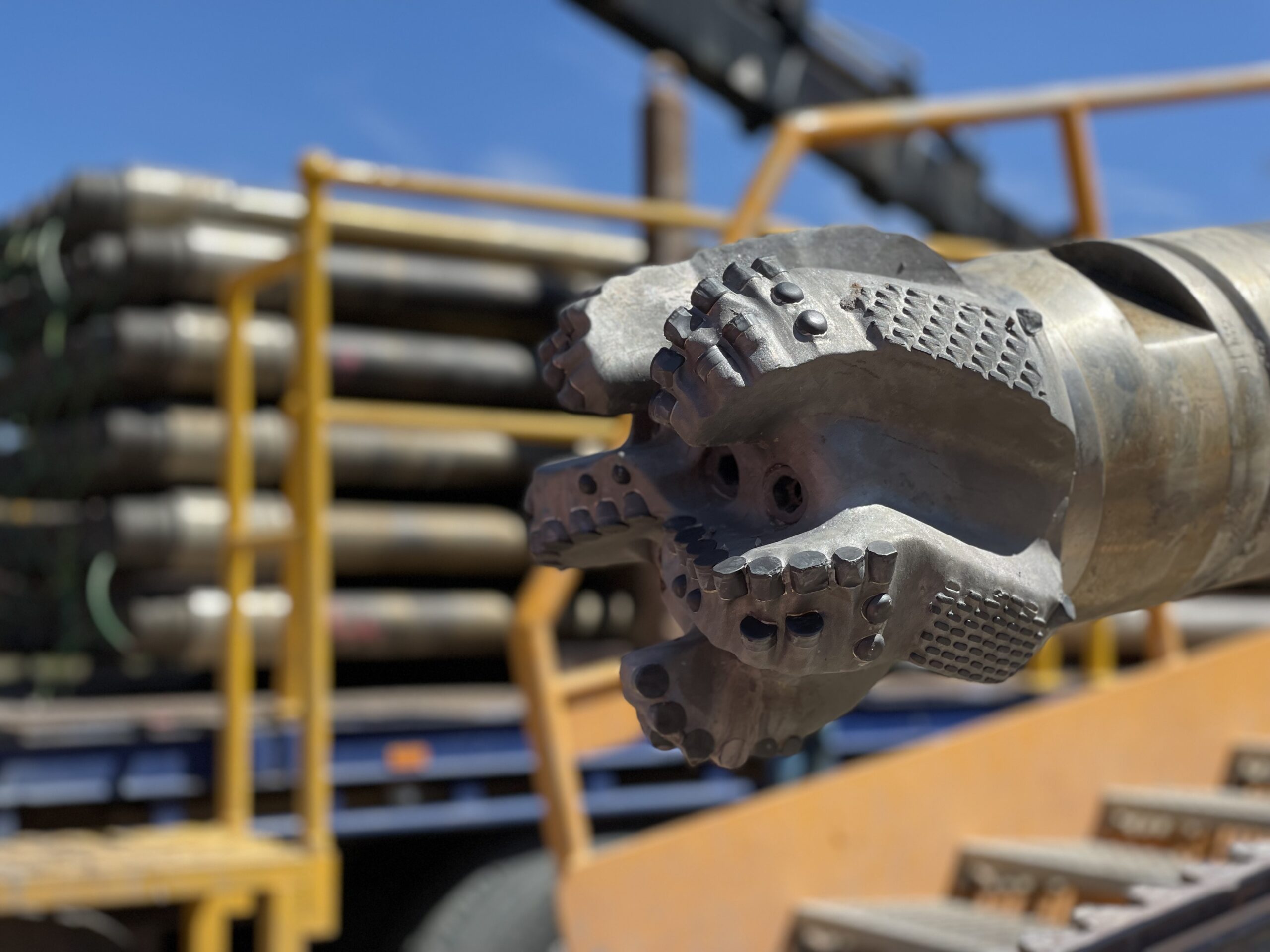
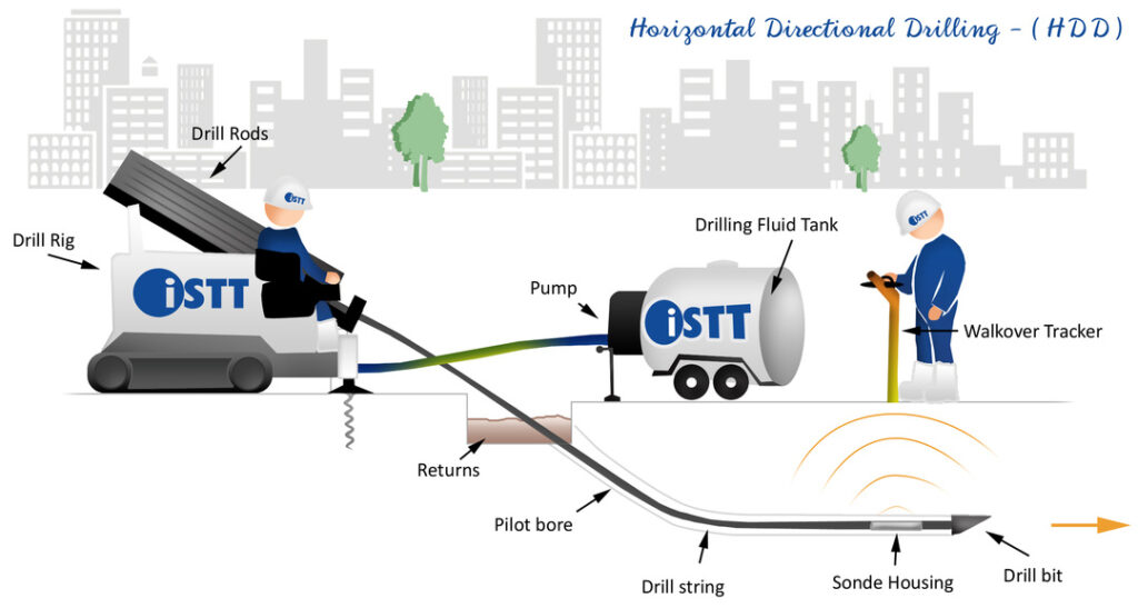
HDD is a multi-pass trenchless construction method where a borehole is drilled from entry to exit, increased to the appropriate size, before pulling the pipe into the borehole. The BHA (Bottom Hole Assembly) is the leading selection of tools in front of the drill pipe, a variety of different BHAs are used throughout the project. This method is reliant on drilling fluid to suspend and transport excavated material (cuttings) from downhole up to surface, as well as minimising borehole collapse.
- A pilot hole is drilled from the HDD rig at the entry location, underground, up to the exit location. The HDD rig pushes the drill pipe down hole to advance the drilling and rotates the drill pipe to break friction and to steer. The BHA for this pass includes a drill bit, bent section, steering equipment, and a motor when drilling in rock conditions.
- Once the pilot bore has been established between entry and exit, the diameter can be increased in stages until the appropriate size bore is reached. This is achieved by pulling a reaming BHA, of larger diameter than the pilot drill bit, towards the rig (conventional back-reaming method) or pushing the reaming BHA away from the HDD rig (non-conventional forward reaming). Multiple ream passes may be required, this minimises the cut area ensuring appropriate circulation and minimising torsional stresses.
- Once the bore is reamed to the appropriate size, it is best practice to clean and gauge the borehole by pulling a cleaning BHA through the borehole. The cleaning BHA should be slightly smaller in OD than the final ream size to agitate any excavated material that has dropped out of suspension, maximise drilling fluid circulation and identify any potential obstructions. Intermediate cleaning passes may also be required between reaming passes, to assess if this is necessary monitor volume of excavated material and downhole tooling torque.
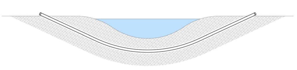
- Best practice drilling includes undertaking a cleaning pass once the reaming is complete.
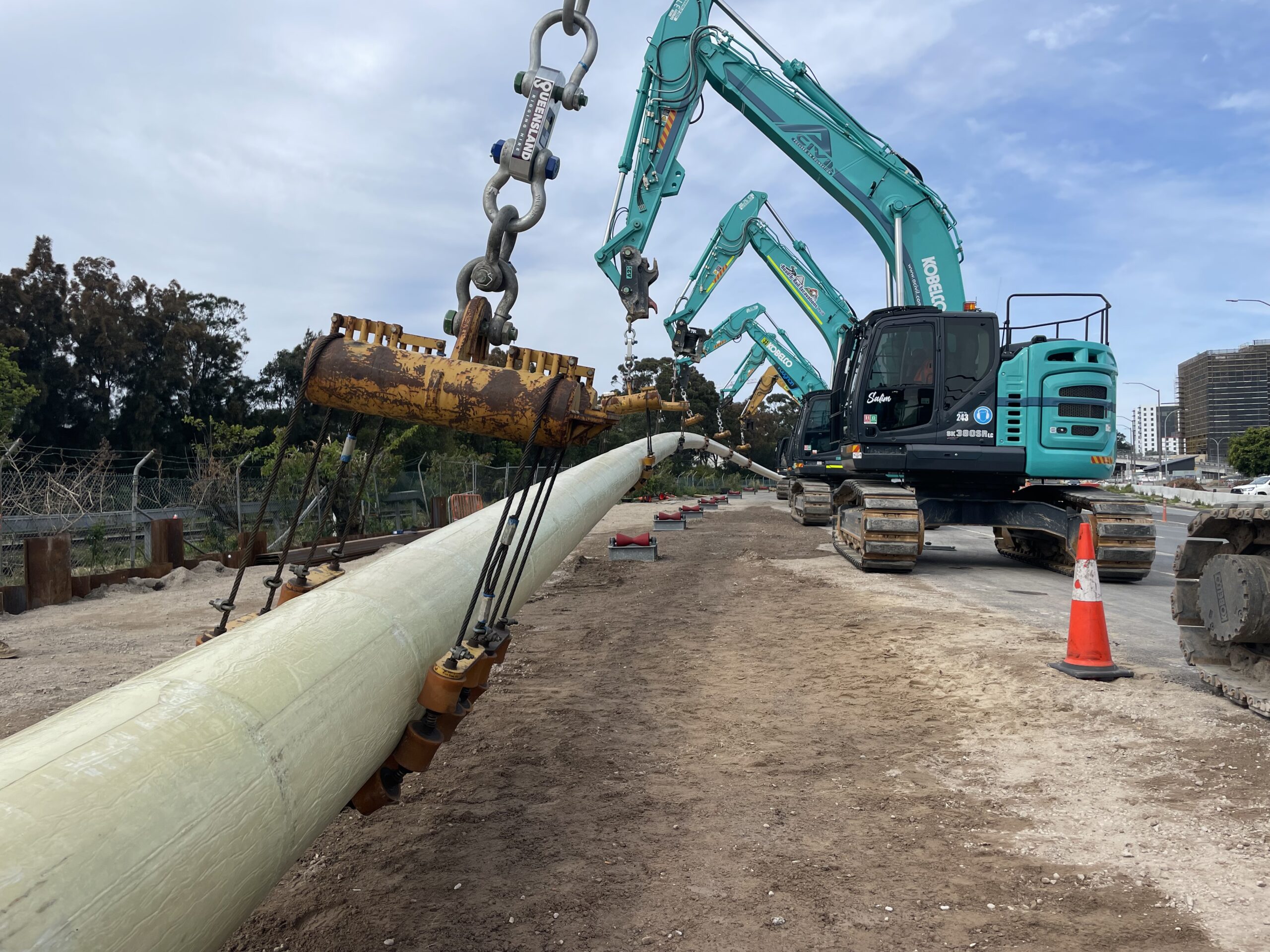
- Once the borehole is ready, the product pipe can be installed into the borehole.
MTBM – Microtunnelling
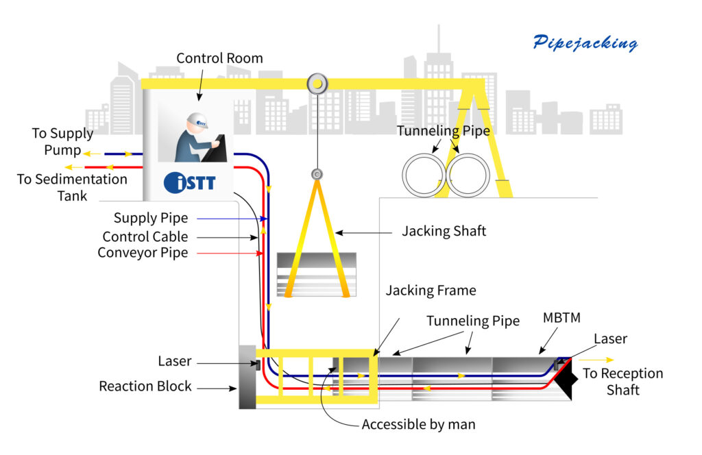
Microtunneling is a precise and controlled method for tunneling and installing pipelines beneath various obstacles, such as highways, railways, rivers, and environmentally sensitive areas. It involves the use of a Microtunnel Boring Machine (MTBM) that is remotely controlled and guided from a launch shaft to a receival shaft.
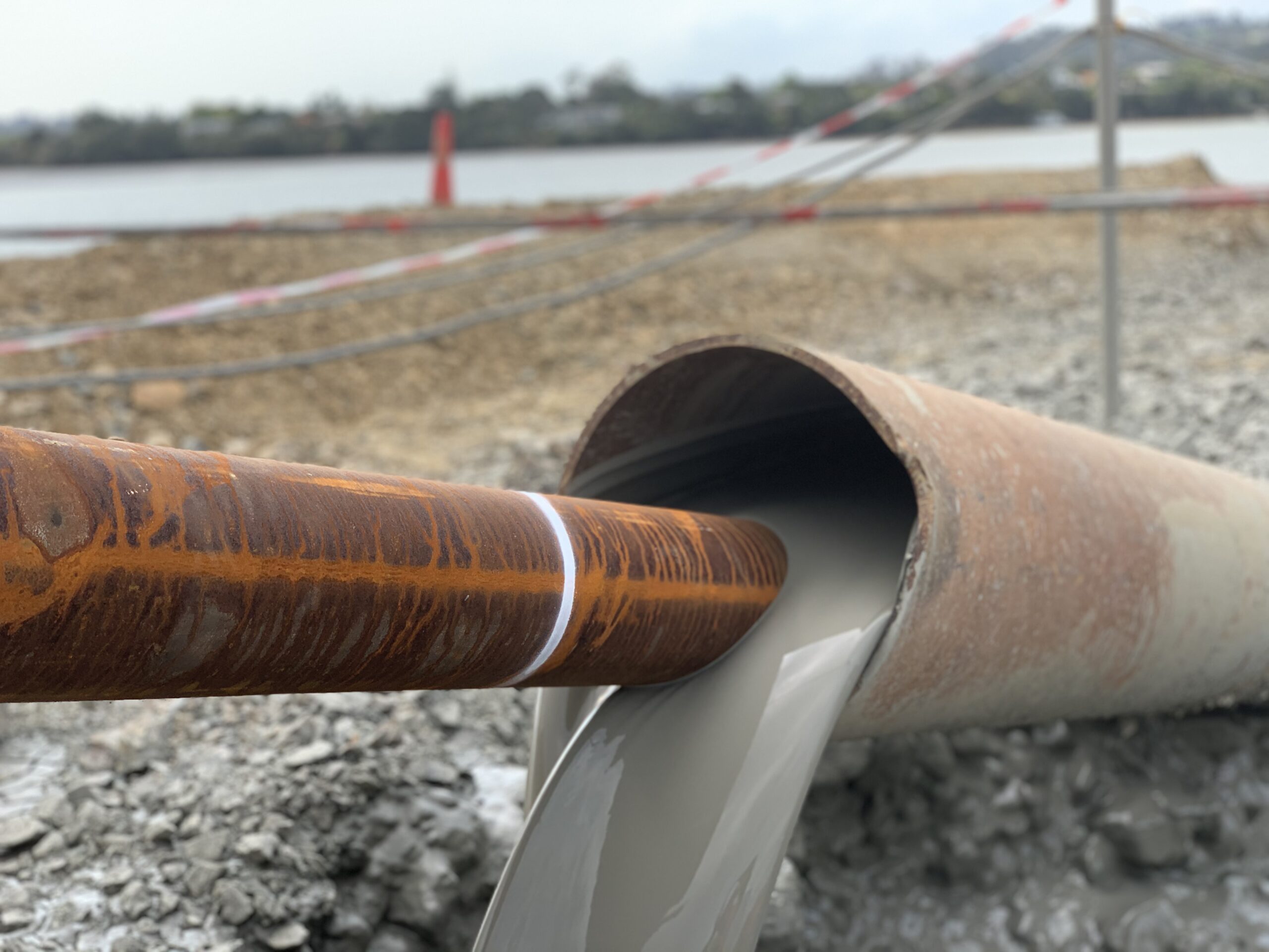
The MTBM is pushed into the ground from a launching shaft, and as it advances, a product pipe or casing is simultaneously inserted behind it. Slurry or other methods are used to balance earth and groundwater pressures at the excavation face, ensuring stability. This technique is particularly suitable for smaller diameter tunnels, and its key features include precise guidance systems, various face support methods, and efficient spoil handling systems.
The MTBM unit is comprised of:
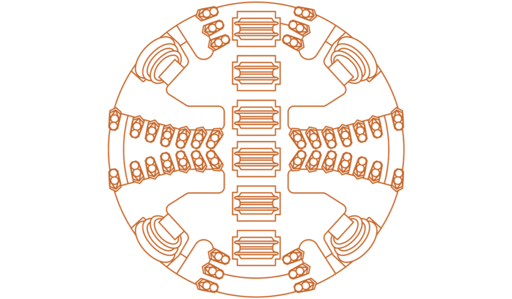
- Rotating cutter head for rotation and excavation
- Cutting discs or teeth selected for expected ground conditions
- Sheild, providing excavation support above excavation
- Conveyor or slurry system, transports the cuttings through pipe back to the launch shaft
- Face support system; slurry, earth-pressure balance, mechanical
- Guidance system; laser or gyroscopic
The method’s terminology has evolved to encompass a range of tunnel diameters and the ability to work in challenging ground conditions.
Although ‘pipe jacking’ is often used interchangeably with microtunnelling, pipe jacking can also be used to describe the group of methods using jacks to thrust pipes hydraulically, such as auger boring. For clarity, the term pipe jacking is only used to describe the group of thrust methods.
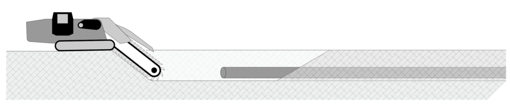
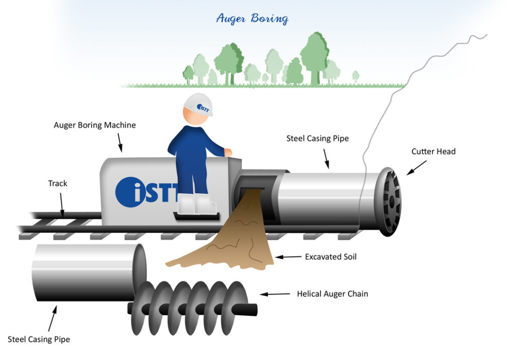
HAB – Horizontal Auger Boring
Auger boring is a reliable and efficient trenchless construction method commonly used for installing steel casing pipes in soft and stable ground conditions, such as clay or soils with contained cobbles, ideally above the water table. This technique is favored for projects involving utilities under sensitive areas like railroads, highways, and levees, where preventing ground settlement and surface disruption is crucial.
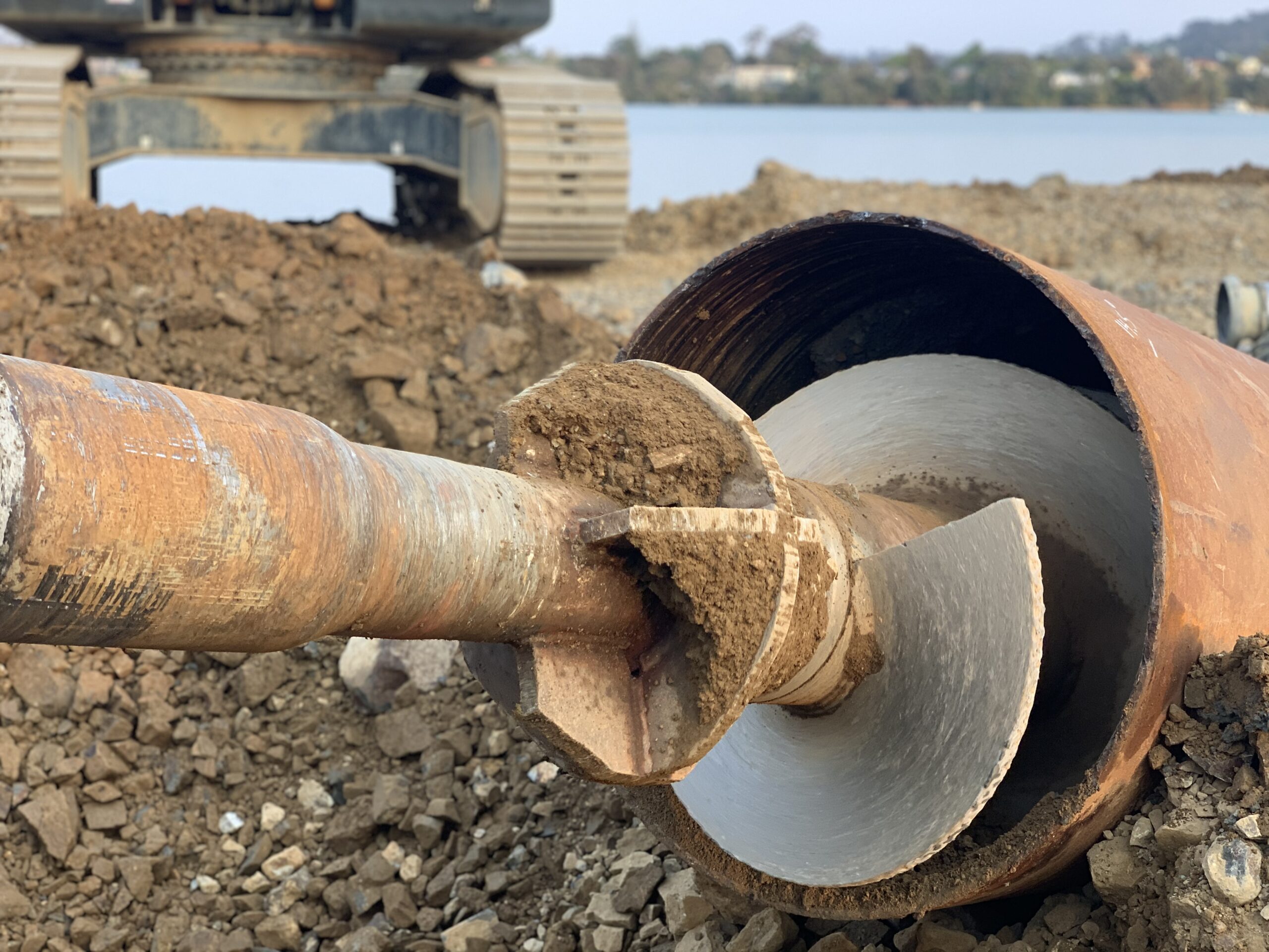
The auger boring process employs a specialized machine with a rotating auger chain or flight situated within a casing pipe, connected to a cutter head at the front of the casing. The cutter head, slightly larger in diameter than the casing pipe, excavates the soil ahead of the casing. The soil is then transported back to the machine via the helical auger chain, where it can be removed manually or with machinery.
The auger boring machine progresses along a track that is precisely aligned to drive the casing pipe along the designated installation path. When the machine reaches the end of the track, the auger chain is disconnected, and the machine is moved back to the starting point on the track. Here, a new casing segment is welded to the existing one, and a new auger chain is connected to the machine and the existing chain and cutter head. This process of excavation and thrust is repeated until the project is completed. Once the auger chain has been withdrawn from the casing pipe, the pipe is thoroughly cleaned of any remaining soil, leaving it ready for utility installation.
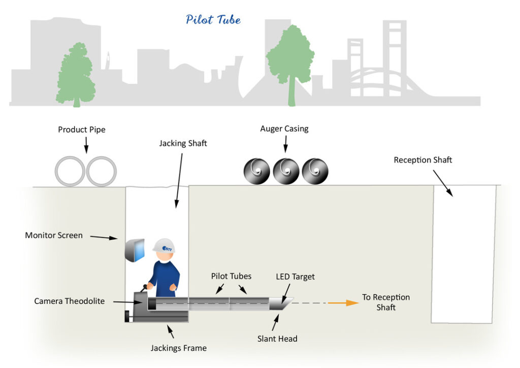
The pilot tube method, or “guided boring,” is an optional step prior to augering for establishing accurate alignments between two sides of a crossing. It relies on a small steel tube which is thrust through displaceable ground with a slant head to maintain a straight path, similar to HDD steering techniques. Line and grade monitoring is accomplished through a digital theodolite, sighting down the pilot tube toward an illuminated LED target at its front, providing data on head position and steering orientation. After pilot tube installation, the excavation and installation process continues by augering as detailed above.
DSPT – Direct Steerable Pipe Thrusting
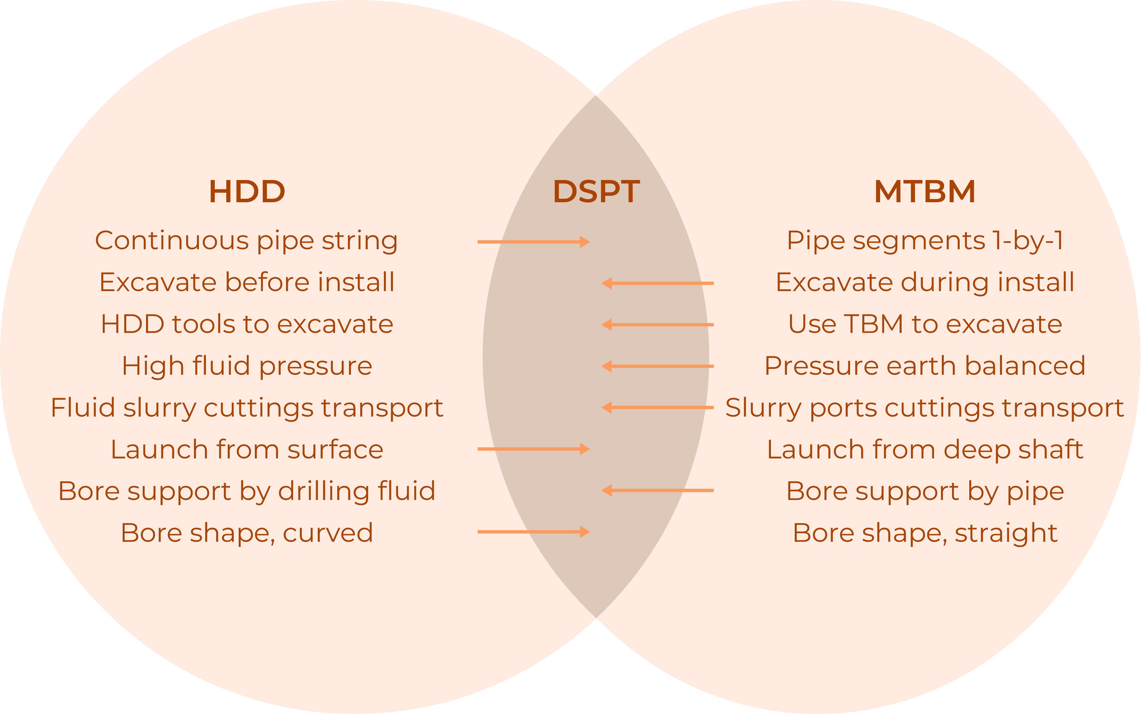
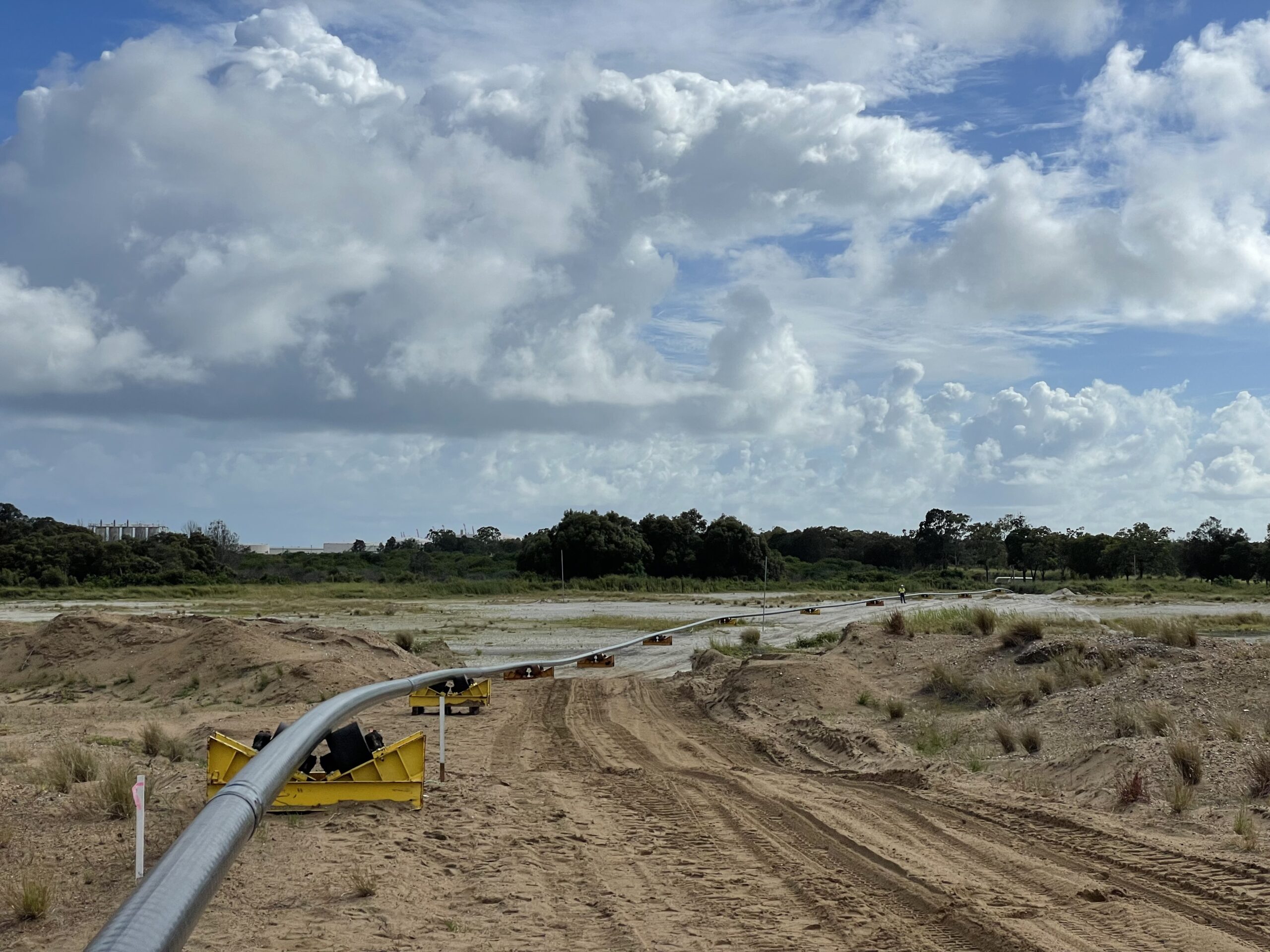
One of the most recent trenchless methods to be developed, Direct Steerable Pipe Thrusting (DSPT), known as the DirectPipe® method, represents a hybrid technique combining elements of HDD and microtunneling.
Here, a slurry microtunneling machine undertakes soil excavation and is navigated along the pre-planned route. The microtunneling machine is securely attached to the leading end of a long continuous steel pipe, unlike short pipe segments used in microtunneling, which progresses through the soil. The propulsion for advancing both the pipe and microtunneling machine is achieved via pipe thrusting, a pipe gripping mechanism at the launch pit, the continuous pipe string minimisies stoppages during installation. This method enables the installation of large-diameter pipes in a single pass, maintaining a minimal annular gap around the pipe throughout installation, thus preventing borehole collapse.
Additionally, it significantly reduces space requirements for on-site work and installation, typically only necessitating one side of the crossing. In cases where space is restricted on the launch side, multiple sections of pipe string can be joined together during the installation process.
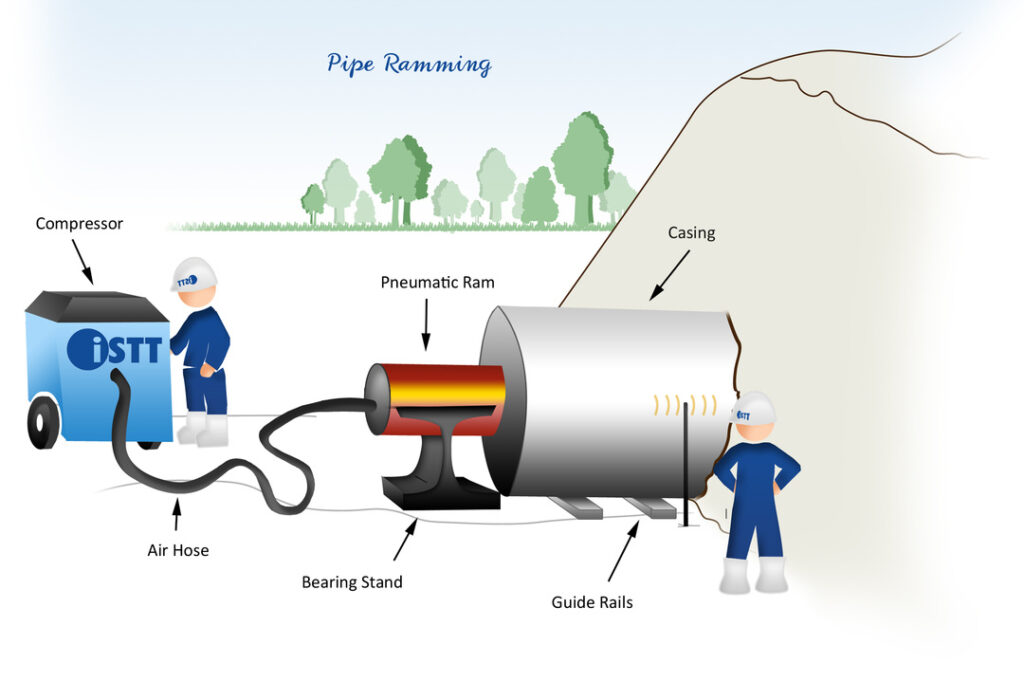
Hammering Or Pipe Ramming
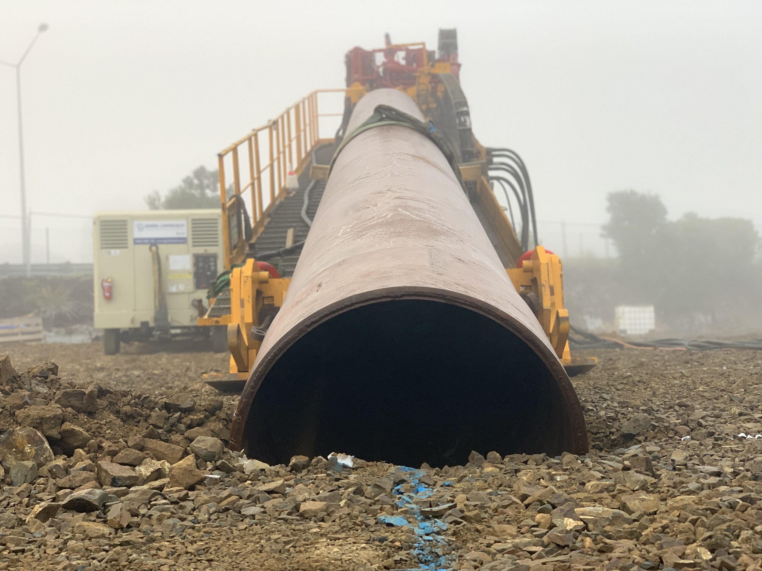
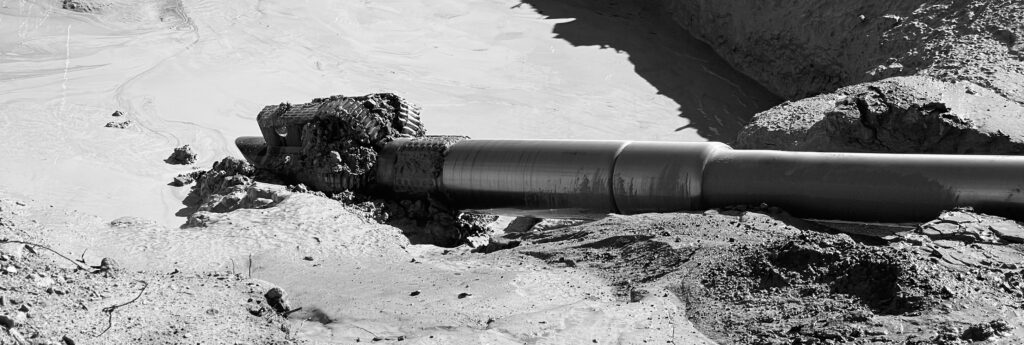
Pipe ramming or hammering, is a highly effective trenchless method primarily used for installing steel casing pipes beneath roads, railroads, and other structures. Unlike other methods, the casing used in pipe ramming is open-ended, allowing soil to enter it during the installation process. This approach significantly minimises the potential for surface settlement, enables the casing to be installed at relatively shallow depths, and may be used in challenging soil conditions, including flowing sands, gravel, cobbles, and even boulders.
The pipe ramming process is straightforward and robust. A product or casing pipe, equipped with a cutting shoe, is positioned on a hammering frame/ guide rails, to direct the pushing of the casing into the soil along the designated alignment. Powered by compressed air, a pneumatic hammer is securely attached to the casing using a cone or collet/ collar system. The hammer delivers powerful impacts, driving the open-ended casing pipe through the soil to the exit area. Additional pipe lengths are welded onto the casing to extend the drive length. Soil may be partially removed during installation to reduce the weight of the casing. To finalise the installation, the soil contained within the casing is typically removed using water, air-pressure, or an auger.
Additional hybrid hammer methods include:
- Whilst hammering is generally undertaken in a forward manner, custom casing attachments can be used to hammer backward and remove casing.
- Pipe ramming may be undertaken to install surface casings through difficult soil conditions at the entry or exit areas for an HDD crossing.
- For long installations, lubricant systems that can be used to reduce pipe friction.
- Prior to hammering, a pilot hole can be undertaken to establish an accurate path.
- In hard rock conditions, a downhole hammer drill may be a suitable tooling option for HDD projects, or percussive ramming may be applied in combination with pipe jacking methods.
Other Trenchless Methods
The above covers the predominant ‘New Installation’ methods for installing pipelines. Other trenchless sectors include:
Allied Technologies
- Mole Ploghing
- Mini-Trench
- Conventional Tunnelling
- Impact Moling
Rehabilitation
- Replacement Slip Lining
- Pipe Splitting or Bursting
- Pipe Reaming or Eating
- Inserted Liner
- Repair
Investigation
- Asset Location
- Ground Investigation
- Asset Inspection
- Performance Assessment